|
Artículo Científico / Scientific Paper |
|
|
|
|
https://doi.org/10.17163/ings.n32.2024.09 |
|
|
|
pISSN: 1390-650X / eISSN: 1390-860X |
|
|
OPTIMIZING STRUCTURAL INTEGRITY OF FIGHTER AIRCRAFT WING STATIONS: A FINITE ELEMENT ANALYSIS APPROACH |
||
|
OPTIMIZACIÓN DE LA INTEGRIDAD ESTRUCTURAL DE LAS ESTACIONES DE ALA DE AERONAVES DE COMBATE: UN ENFOQUE DE ANÁLISIS DE ELEMENTOS FINITOS |
||
|
Received: 02-05-2024, Received after review: 29-05-2024, Accepted: 13-06-2024, Published: 01-07-2024 |
|
Resumen |
|
|
Modern fighter aircraft are equipped with multiple stations on the fuselage and under the wings to accommodate various external stores, both jettisonable and non-jettisonable. Each configuration undergoes airworthiness certification, including structural analysis of individual stations within the carriage flight envelope. This study focuses on the structural analysis of a fighter aircraft wing station within this specified envelope. To perform this analysis, the wing station is extracted from the comprehensive global wing model, creating a sub-model with equivalent stiffness properties. Utilizing ANSYS Workbench®, Finite Element Analysis (FEA) is conducted for critical load cases to determine the Factor of Safety (FoS). The initial analysis reveals that the wing station has an FoS of 1.2 under the maximum design load. Prestressed modal and buckling analyses indicate a 10% increase in stiffness due to stress-stiffening effects. To further enhance load-carrying capacity, parametric design changes are introduced. Increasing the bolt diameter from 8 mm to 10 mm raises the FoS to 1.33, resulting in an 8% increase in the maximum load-carrying capacity of the wing station. This comprehensive approach, employing FEA, ensures the wing’s structural integrity under static load conditions within the carriage envelope. The study’s findings support the wing station’s enhanced performance and contribute to safer and more efficient aircraft operations. |
Los aviones de combate modernos están equipados con múltiples estaciones en el fuselaje y debajo de las alas para acomodar varios almacenes externos, tanto descartables como no descartables. Cada configuración se somete a una certificación de aeronavegabilidad, incluido un análisis estructural de las estaciones individuales dentro de la envolvente de vuelo del transporte. Este estudio se centra en el análisis estructural de una estación de ala de un avión de combate dentro de esta envolvente especificada.Para realizar este análisis, la estación del ala se extrae del modelo global integral del ala, creando un submodelo con propiedades de rigidez equivalentes. Utilizando ANSYS Workbench®, se realiza un análisis de elementos finitos (FEA) para casos de carga críticos para determinar el factor de seguridad (FoS). El análisis inicial revela que la estación del ala tiene un FoS de 1,2 bajo la carga máxima de diseño. Los análisis modales y de pandeo pretensados indican un aumento del 10 % en la rigidez debido a los efectos de rigidez por tensión. Para mejorar aún más la capacidad de carga, se introducen cambios de diseño paramétrico. El cambio del diámetro del perno de 8 mm a 10 mm incrementa el FoS a 1,33, lo que da como resultado un aumento del 8 % en la capacidad máxima de carga de la estación del ala. Este enfoque integral, que emplea FEA, garantiza la integridad estructural del ala bajo condiciones de carga estática dentro de la envolvente del carro. Los hallazgos del estudio respaldan el rendimiento mejorado de la estación del ala y contribuyen a operaciones de aeronaves más seguras y eficientes. |
|
|
|
|
Keywords: External store; Weapon Carriage; Static Structural Analysis; Sub-modelling; Modal Analysis; Buckling Analysis; Design Optimization |
Palabras clave: tienda externa, transporte de armas, análisis estructural estático; submodelado, análisis modal, análisis de pandeo, optimización del diseño |
|
1,*Instituto de Aeronáutica y Astronáutica, Universidad Aérea de Islamabad, Pakistán. Corresponding author✉: aunbhutta@gmail.com.
Suggested citation: Haider Bhutta, Aun. “Optimizing Structural Integrity of Fighter Aircraft Wing Stations: a Finite Element Analysis Approach,” Ingenius, Revista de Ciencia y Tecnología, N.◦ 32, pp. 90-100, 2024, doi: https://doi.org/10.17163/ings.n32.2024.09. |
|
In the last two decades, there has been a notable upswing in the adoption of the finite element method (FEM) for the analysis of complex structures [1]. This numerical technique provides a highly accurate approximate solution for problems that lack closed-form solutions. In static structural finite element analysis (FEA), constitutive laws describe how materials respond to applied loads and define the relationship between stress and strain. Hooke’s Law, presented in Equation (1), is the fundamental constitutive law employed for linear elastic materials. This law provides a linear relationship between the stress (σij) and strain tensors (ϵkl), represented as follows:
Cijkl is the elastic stiffness tensor, which depends on material properties such as Young’s modulus E and Poisson’s ratio (ν) In a practical FEA scenario, several variables are known, including material properties (Young’s modulus, Poisson’s ratio and density), geometry (dimensions and shape of the structure), and boundary conditions (displacements such as fixed supports or prescribed movements, and forces such as applied loads or pressure). In FEA, unknown quantities include nodal displacements (ui) at each node in the mesh, as well as strains (ϵij) and stresses (σij) at each integration point or node. For a linear elastic material in 3D, the stiffness matrix can be expressed using Lame’s constants, λ and G, derived from Young’s modulus and Poisson’s ratio.
Equation (3) presents stress-strain relationship in matrix form.
By inputting the known material properties and boundary conditions into the FEA software, the unknowns (displacements, strains, and stresses) can be determined. This process ensures accurate prediction of structural behaviour under applied loads, facilitating the design and assessment of structural integrity. A review of published research reveals the prevalent use of fixed boundary conditions (BC) in the static structural analysis of members isolated from the global structure [2]. While commonly employed, it is acknowledged that this boundary condition represents a conservative approximation, which overestimates the maximum stress on the structural member, consequently leading to an underestimation of the Factor of Safety (FOS) [3]. The use of fixed support boundary conditions in the analysis of statically indeterminate structures, such as aircraft |
wings, presents notable limitations primarily due to the assumptions that fixed supports introduce, which may not accurately reflect real-world conditions [4]. Fixed supports assume no movement or rotation at the support points, which is often unrealistic in practical scenarios. Aircraft wings experience various forces and moments that cause deformations, significantly influencing overall structural behaviour [5]. Additionally, joints and connections in an aircraft are not perfectly rigid; they possess some degree of flexibility which must be considered for a more accurate structural analysis. Fixed supports can misrepresent actual load paths and stress distributions within the structure. Aircraft wings are engineered to distribute loads efficiently, but fixed supports can alter these distributions, leading to inaccurate analyses [6]. This can result in artificial stress concentrations that do not exist in the structure, potentially leading to erroneous assessments of structural integrity and fatigue life. Moreover, fixed supports simplify the boundary conditions to a degree that may not accurately capture material non-linearities, such as plastic deformation and creep [7]. Aircraft wings frequently operate under conditions where these material non-linearities are significant, necessitating boundary conditions that can account for such effects. Additionally, large deformations and geometric non-linearities in aircraft wings require boundary conditions that can adapt to changing configurations, a capability that fixed supports cannot provide. Lastly, results from analyses using fixed supports may not correlate well with experimental data or inflight measurements. To ensure accurate and reliable analysis, engineers often resort to more realistic boundary conditions that simulate the interaction between different parts of the structure, and flexible supports that incorporate the elasticity of attachments and connections. Hybrid models, combining various boundary conditions, are also employed to better capture the complex interactions within the structure. These advanced boundary conditions facilitate more accurate predictions of structural behaviour under diverse loading conditions, leading to safer and more efficient aircraft designs. The wing of an aircraft is classified as a statically indeterminate structure [8]. Such structures feature kinematic redundancy, wherein the constraints exceed the minimum necessary to prevent rigid body motion under applied loads. In statically indeterminate structures, the values of reaction forces and moments at supports are influenced by the stiffness characteristics of the structure [9]. Consequently, the stiffness of the wing plays a crucial role in determining the load distribution on the tulips of the wing station [10]. Rather than imposing a fixed boundary condition on a local model isolated from the global model, an alternative approach involves assigning nodal displacements derived from the solution of the global Finite Element (FE) model [11]. An FE analysis of the isolated structural member, incorporating these nodal displacements and the applied load, is conducted to obtain accurate results. This method requires solutions for both the global and local models for each load case [12]. |

|
A third technique involves isolating the local model from the global model using translational and rotational springs. The stiffness of these springs depends on the deformation field of the global model under the applied load [13]. Subsequently, a refined local model is analysed using these springs for each load case. Implementing these springs in ANSYS is accomplished by applying elastic support boundary conditions, with stiffness derived from analysing the global wing model under design load [14]. This examination focuses on a contemporary jet fighter aircraft. Figure 1 depicts the wing of an aircraft, including four spars: the Front Wall Spar, Front Spar, Main Spar, and Rear Spar [15]. These spars constitute a cohesive framework intricately interconnected through a system of 12 ribs.
Figure 1. Internal Structure of Aircraft Wing [15]
This study focuses on outboard wing station 2/6, located on Wing Rib 7, specifically designated for carrying external stores. This station comprises two integral structural components: the Front Tulip (FT) and the Rear Tulip (RT). Considering the limitations of fixed boundary conditions, this study enhances the analysis fidelity by incorporating wing stiffness. The primary aim is to ascertain the maximum load-carrying capacity of wing station 2/6, employing accurate boundary conditions through the sub-modelling technique [16]. This method aims to provide a more accurate portrayal of structural behaviour, enabling precise evaluation of stress levels and FOS for the wing station. Incorporating wing stiffness enhances reliability of structural analysis and provides nuanced insights into wing performance under diverse conditions. Sub-modelling techniques account for the influence of wing stiffness, resulting in improved accuracy and understanding of structural behaviour. Ultimately, integrating wing stiffness enhances structural analysis reliability, offering valuable insights into wing performance across various scenarios.
2. Materials and Methods
The methodology involves extracting the front and rear tulips from the global wing model and introducing wing stiffness via elastic boundary conditions derived from FE analysis under the design load [17]. Critical loads are |
applied to each wing tulip, and static structural analysis is conducted in ANSYS Workbench version 14.5 to generate deformation and stress field. Utilizing the Factor of Safety (FOS) based on yield strength, the study determines the maximum load-carrying capacity of the wing station. Prestressed modal and buckling analyses [18] are performed to assess the stress-stiffening effect under the maximum design load. The real potential of this study lies in the design optimization, which is implemented through parametric alterations of the bolt holes of the wing tulip. This process enhances the load-carrying capacity of the wing station, facilitating a comprehensive evaluation of structural performance and enhancing the overall capabilities of the fighter aircraft [19]. While this study provides a comprehensive understanding of the wing station’s behaviour under static loads, it does not account for cyclic loading conditions. PSD analysis for cyclic loading will be addressed in subsequent studies.
3. Results and Discussion
3.1. Boundary Conditions for Tulips
The FE model of the wing, constructed using line and shell elements, is illustrated in Figure 2. Analysis of this wing model under design load generates a displacement field depicted in Figure 3. The resulting displacement field under applied loads provides stiffness values for the elastic support imposed as a boundary condition for the analysis of the Front and Rear Tulips.
Figure 2. FE Model of the Wing [9]
Figure 3. Deformation Field of the Wing |


|
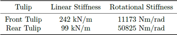
The stiffness values for the respective elastic supports, obtained through ANSYS Workbench version 14.5, are presented. These stiffness values are utilized in the analysis of isolated wing tulips. Loads applied to the wing are transferred to the fuselage, causing deformation and motion at the aircraft’s center of gravity. To eliminate rigid body motion in the analysis, it is necessary to constrain the aircraft’s centreline. In the current study, the wing model of the aircraft is constrained to six degrees of freedom (6 DOF) at the aircraft’s centreline. This constraint prevents undesired rigid body motions, ensuring an accurate load transfer and structural behaviour simulation. By applying these constraints, the analysis provides stable and realistic boundary conditions for the Finite Element Analysis (FEA).
3.2. FE Models of Tulips
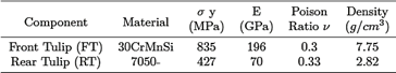
CAD models of the front and rear tulips for wing station 2/6, which have been developed in the ANSYS Design Module®, are illustrated in Figure 4 and Figure 5, respectively. These CAD models serve as templates for developing FE models in ANSYS Workbench®. Material properties assigned to the wing tulips are detailed in the aerodynamic analysis of aircraft with external stores within the carriage envelop of the aircraft, providing provides critical load cases for wing tulips [1]. Table 3 and Table 4 comprehensively outline the load cases exerted on the Front Tulip (FT) and Rear Tulip (RT) during the carriage envelop [1]. These forces and bending moments are applied to both the front and rear tulips of station 2/6.
Table 1. Elastic Boundary Condition for Tulips [9]
Figure 4. Solid Model of the Front Tulip (FT) [9]
Figure 5. Solid Model of the Rear Tulip |
Table 2. Material Properties of Tulips
Table 3. Loads Cases (LC) for the Front Tulip (FT) force in kN and moments in kN.m) [1]
Table 4. Load Cases (LC) for the Rear Tulip (RT) (force in kN and moments in kN.m) [1]
3.3. Analysis of the Front Tulip (FT)
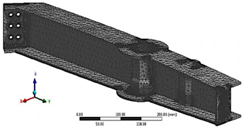
The model has been free-meshed using Tet6 elements, which are tetrahedral-shaped elements with three nodes and a quadratic shape function. To ensure accuracy, the mesh is refined at stress hot spots located at bolt holes. As illustrated in Figure 6, a mesh independence study establishes that the solution becomes independent of mesh refinement at 70,000 elements. Figure 7 displays the meshed model of the Front Tulip (FT), while Figure 8 illustrates the applied boundary conditions and loads on the FT.
Figure 6. Grid Independence of the FT |


|
Figure 7. Free Mesh of the FT [9]
Figure 8. Loads and Boundary Conditions on the FT
For each load case, deformation and stress plots are generated in ANSYS. The comparison of maximum equivalent (von Mises) stress for each load case on the Front Tulip (FT) is illustrated in Figure 9. Load Case No. 4 is identified as the critical load case for the FT, with a stress value of 674 MPa. The deformation field of the Front Tulip under critical Load Case No 4 is depicted in Figure 10. A maximum deformation of 0.13 mm is observed on the flange of the FT.
Figure 9. Max Stress for the FT under all LCs |
Figure 10. Deformation of the FT under LC No 4
Further insight into the structural response, namely the resultant stress field and Factor of Safety (FOS), is provided in Figure 11 and Figure 12, respectively. The FOS of the Front Tulip (FT) is 1.23 under critical Load Case No. 4, indicating that the FT is safe within the carriage envelop. These analyses contribute to a comprehensive understanding of the structural behaviour, assessing safety margins and identifying potential areas for design optimization.
Figure 11. Equivalent Stress of the FT under LC No 4
Figure 12. FOS of the FT under LC No 4 |


|
3.4. Analysis of the Rear Tulip (RT)
The free meshing of the rear tulip model has been conducted using Tet6 elements, which are tetrahedralshaped elements with three nodes and a quadratic shape function. Mesh refinement at bolt holes is implemented to capture the large stress gradient at these hot spots. A mesh independence study, as illustrated Figure 13, demonstrated that the solution became independent of mesh refinement at 130,000elements. Figure 14 illustrates the meshed model of the Rear Tulip (RT). Figure 15 illustrates the boundary conditions and applied loads, represented as forces and moments.
Figure 13. Mesh Independence for the RT
Figure 14. Free Mesh for the RT
Figure 15. Boundary Condition and Loads for the RT
Through Finite Element (FE) analysis, deformation and stress for each load case were determined. The comparison of maximum equivalent (von Mises) stress for each load case on the Rear Tulip (RT) is presented in Figure 16. The critical load case for RT is identified as Load Case No 21, exhibiting a stress value of 323 MPa. Figure 17 illustrates the deformation field of the Rear Tulip under Load Case No. 21. A maximum deformation of 0.83 mm is observed under this critical LC. |
Figure 16. Max Stress for all LCs on the RT
Figure 17. Deformation of RT under LC No 21
Additional insights into resultant stress field and Factor of Safety (FOS) under this specific load case is provided in Figure 18 and Figure 19. FOS of RT is 1.3 under the critical LC NO 21 which indicates that RT is safe within the carriage envelop. These comprehensive analyses contribute to a detailed understanding of the structural behaviour, aiding in assessment of safety margins and potential areas for design optimization of Rear Tulip.
Figure 18. Equivalent Stress of the RT under LC No 21
Figure 19. FOS of the RT for under LC No 21 |


|
3.5. Modal and Prestressed Modal Analysis
Modal analysis of the Front and Rear Tulips of the wing station has been conducted to explore the dynamic characteristics of free vibrations without external forces [20]. This analysis used free mesh models of the Front and Rear Tulips within the ANSYS Modal Module. The fundamental mode shapes for the Front and Rear Tulips are depicted in Figure 20 and Figure 21, respectively. The fundamental mode frequencies for the Front Tulip (FT) and Rear Tulip (RT) are 286 Hz and 282 Hz, respectively.
Figure 20. Fundamental Mode Shape for Free Mesh
Figure 21. Fundamental Mode Shape of the RT
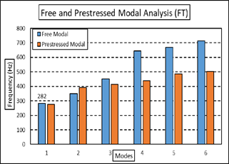
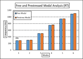
Additionally, a prestressed modal analysis has been conducted to assess stress-stiffening effects. A comparison between free and prestressed modal frequencies for the Front and Rear Tulips is presented in Figure 22 and Figure 23, respectively. The prestressed modal analysis reveals a minimal decrease in modal frequencies for the Front Tulip (FT). For the Rear Tulip (RT), there is no decrease in modal frequency under applied stress. Therefore, the stress-stiffening effect for the FT and RT Tulips is insignificant. |
Figure 22. Free and Prestressed Modal Analysis of the FT
Figure 23. Free and Prestressed Modal Analysis of RT
A comparative analysis offers insights into how prestressed conditions affect the modal behaviour of tulips, shedding light on the structural response under the influence of pre-existing stresses. These findings enhance the comprehensive understanding of the dynamic characteristics of the Front and Rear Tulips.
3.6. Buckling Analysis
Buckling analyses of the Front and Rear Tulips have been conducted to ascertain buckling loads and corresponding buckling mode shapes [21]. The results of these analyses are depicted in Figure 24 and Figure 25, showcasing the first buckling mode for the Front and Rear Tulips, respectively, under their critical load cases.
Figure 24. 1st Buckling Mode of the FT |


|
Figure 25. 1st Buckling Mode of RT
The buckling load multipliers for the front and rear tulips are determined to be 95 and 13, respectively, under critical load cases. These high load multipliers suggest buckling is not a likely failure mode for the wing tulips. The mode shapes provide crucial insights into the structural stability of the tulips under specific loading conditions, enhancing the identification of potential failure modes and the determination of safety margins for the wing station components.
3.7. Optimization
The current radio for all bolt holes of the tulips are 4 mm. This study reveals that the maximum stress under a critical load case occurs at the bolt holes. To conduct a stress sensitivity analysis, the diameter of the bolt holes varies from 6 to 10 mm using the ANSYS Optimization Module [22]. Figure 26 and Figure 27 display the stress response surfaces as a function of bolt-hole radii for the Front Tulip and Rear Tulip, respectively. These surfaces visually demonstrate how changes in bolt-hole radii influence the tulips’ maximum stress. Figure 26 indicates that the radii of bolts on the inboard side (P2) have no discernible impact on the maximum stress value of the Front tulip (P3). Conversely, the radii of bolts on the outboard side (P1) significantly influence the maximum stress value of the Front tulip. Initially, increasing the radii of bolt holes on the outboard side from 3 mm results in an increase in the maximum stress value (P3) up to 3.5 mm; beyond this point, further increases lead to a decrease in the maximum stress value. Figure 27 demonstrates that the radii of bolt holes on both the front (P1) and rear (P2) sides of the Rear Tulip significantly impact the maximum stress value (P3). Initially, as the values of P1 and P2 increase from 3 mm, the maximum stress value decreases, reaching a minimum of 4.5 mm. However, further increases in the radii of the bolt holes increase the maximum stress value. This sensitivity analysis reveals that the minimum stress for the Front Tulip occurs with a bolt-hole radius of 5 mm, while for the Rear Tulip, a radius of 4.5 mm is optimal. These design parameters reduce the maximum stress to 627 MPa and 286 MPa for the Front and Rear Tulips, respectively. |
The larger bolt holes contribute to an increased Factor of Safety (FOS) of 1.33. Consequently, the maximum load-carrying capacity of the wing station increases from 653 kg to 706 kg with this optimized design. This sensitivity analysis is crucial for optimizing the design of bolted connections in tulips, helping to identify the most suitable diameter that minimizes stress concentrations and enhances the overall structural performance of the Front and Rear Tulips.
Figure 26. Response Surface for Max Stress FT
Figure 27. Response Surface for Max Stress RT
4. Conclusions
This study addresses a significant gap in the stateof-the-art application of similar research problems by focusing on the influence of stiffness characteristics on the maximum load-carrying capacity of a fighter aircraft’s wing. Although previous studies have explored various factors affecting the structural integrity of aircraft components, few have delved into the role of wing stiffness and its direct impact on load-carrying capacity. This research integrates wing stiffness into the Finite Element (FE) model of isolated tulips, providing an analysis that accurately predicts the structural integrity of the weapon station. Additionally, using sub-modelling as a versatile and computationally efficient technique introduces an innovative methodology, bridging a gap in the existing literature by showcasing its applicability to intricate structural components with minimal computational expense. |


|
Validation of the initial hypothesis through obtained data underscores the significance of wing stiffness in assessing the wing station’s maximum loadcarrying capacity. Overall, this research enhances the understanding of structural analysis in aerospace engineering by providing novel insights and methodologies to address a critical gap in the field. The key findings of this research are outlined as follows:
Front Tulip: • Optimal bolt-hole radius: 5 mm • Reduced maximum stress: 627 MPa Rear Tulip: • Optimal bolt-hole radius: 4.5 mm • Reduced maximum stress: 286 MPa Factor of Safety (FOS): • Increased to 1.33 with larger bolt holes Maximum Load-Carrying Capacity: • Increased from 653 kg to 706 kg with the optimized design
Identifies critical design parameters for optimizing bolted connections in tulips, helping to determine the most suitable diameter that minimizes stress concentrations and enhances the overall structural performance of both the Front and Rear Tulips. A notable limitation of this research is the exclusion of fasteners from the analysis, predicated on the assumption of perfect load transfer between the structural elements of the wing and the wing tulips. Consequently, this study does not account for the potential failure modes associated with fasteners. Future research endeavours should explore the following aspects to enhance the comprehensiveness of structural analyses. Addressing these aspects would significantly contribute to the structural assessments of large assemblies.
Non-linear Effects: • Implications of non-linear effects on structural integrity. Mesh Patterns: • Effects of regular mesh patterns on simulation results. Cyclic Loading / Power Spectral Density (PSD) Analysis: • Cyclic loading and PSD analysis to evaluate longterm structural performance.
Author Contributions
The entirety of this research, including literature review, methodology, results and findings represents work of Author.
Acknowledgments
The author acknowledges the support of his department at Air University for providing all the necessary resources for this publication. |
Conflict of Interest
The author declared no potential conflicts of interest concerning research, authorship, and publication of this article.
Funding
The author received no financial support for research, authorship, and publication of this article.
Data Availability Statements
The current study is available from the corresponding author upon reasonable request.
References [1] K. Sinha, T. Klimmek, M. Schulze, and V. Handojo, “Loads analysis and structural optimization of a high aspect ratio, composite wing aircraft,” CEAS Aeronautical Journal, vol. 12, no. 2, pp. 233–243, Apr 2021. [Online]. Available: https://doi.org/10.1007/s13272-021-00494-x [2] B. D. Upadhyay, S. S. Sonigra, and S. D. Daxini, “Numerical analysis perspective in structural shape optimization: A review post 2000,” Advances in Engineering Software, vol. 155, p. 102992, 2021. [Online]. Available: https://doi.org/10.1016/j.advengsoft.2021.102992 [3] N. Zimmermann and P. H. Wang, “A review of failure modes and fracture analysis of aircraft composite materials,” Engineering Failure Analysis, vol. 115, p. 104692, 2020. [Online]. Available: https://doi.org/10.1016/j.engfailanal.2020.104692 [4] R. L. Muhanna and S. Shahi, Uncertainty in Boundary Conditions—An Interval Finite Element Approach. Cham: Springer International Publishing, 2020, pp. 157–167. [Online]. Available: https://doi.org/10.1007/978-3-030-40814-5_20 [5] T. Martins, V. Infante, L. Sousa, A. Fonseca, P. Antunes, A. Moura, and B. Serrano, “Numerical and experimental study of aircraft structural health,” International Journal of Fatigue, vol. 132, p. 105348, 2020. [Online]. Available: https://doi.org/10.1016/j.ijfatigue.2019.105348 [6] J. Lim, C. You, and I. Dayyani, “Multi-objective topology optimization and structural analysis of periodic spaceframe structures,” Materials & Design, vol. 190, p. 108552, 2020. [Online]. Available: https://doi.org/10.1016/j.matdes.2020.108552 [7] C. Touzé, A. Vizzaccaro, and O. Thomas, “Model order reduction methods for geometrically nonlinear structures: a review of nonlinear techniques,” Nonlinear Dynamics, vol. 105, no. 2, pp. 1141– 1190, Jul 2021. [Online]. Available: https://doi.org/10.1007/s11071-021-06693-9 |
|
Tulip frontal: • Radio óptimo del agujero del perno: 5 mm • Reducción máxima del estrés: 627 MPa Tulip trasero: • Radio óptimo del agujero del perno: 4,5 mm • Reducción máxima del estrés: 286 Mpa Factor de seguridad (FOS): • Aumentado a 1,33 con agujeros de perno más grandes Capacidad máxima de carga: • Aumentada de 653 kg a 706 kg con el diseño optimizado
Identifica parámetros críticos de diseño para optimizar las conexiones atornilladas en las tulip, ayudando a determinar el diámetro más adecuado que minimice las concentraciones de estrés y mejore el rendimiento estructural general tanto de la Tulip frontal como de la Tulip trasero. Una limitación notable de esta investigación es la exclusión de los sujetadores del análisis, basada en la suposición de una transferencia de carga perfecta entre los elementos estructurales del ala y las tulip del ala. Por lo tanto, este estudio no considera los posibles modos de falla asociados con los sujetadores. Los futuros esfuerzos de investigación deberían explorar los siguientes aspectos para mejorar la integralidad de los análisis estructurales. Abordar estos aspectos contribuiría significativamente a las evaluaciones estructurales de grandes conjuntos. Efectos no lineales: • Implicaciones de los efectos no lineales en la integridad estructural. Patrones de malla: • Efectos de los patrones de malla regular en los resultados de simulación. Carga cíclica / Análisis de densidad espectral de potencia (PSD): • Análisis de carga cíclica y PSD para evaluar el rendimiento estructural a largo plazo. |
La totalidad de esta investigación, incluida la revisión de literatura, metodología, resultados y conclusiones, representa el trabajo del autor.
Agradecimientos
El autor agradece el apoyo de su departamento en la Universidad del Aire por proporcionar todos los recursos necesarios para esta publicación.
Conflictos de interés
El autor declara no tener conflictos de interés potenciales en relación con la investigación, autoría y publicación de este artículo.
Financiamiento
El autor no recibió apoyo financiero para la investigación, autoría y publicación de este artículo.
Declaraciones de disponibilidad de datos
El estudio actual está disponible del autor correspondiente previa solicitud razonable.
Referencias
[1] K. Sinha, T. Klimmek, M. Schulze, and V. Handojo, “Loads analysis and structural optimization of a high aspect ratio, composite wing aircraft,” CEAS Aeronautical Journal, vol. 12, no. 2, pp. 233–243, Apr 2021. [Online]. Available: https://doi.org/10.1007/s13272-021-00494-x [2] B. D. Upadhyay, S. S. Sonigra, and S. D. Daxini, “Numerical analysis perspective in structural shape optimization: A review post 2000,” Advances in Engineering Software, vol. 155, p. 102992, 2021. [Online]. Available: https://doi.org/10.1016/j.advengsoft.2021.102992 [3] N. Zimmermann and P. H. Wang, “A review of failure modes and fracture analysis of aircraft composite materials,” Engineering Failure Analysis, vol. 115, p. 104692, 2020. [Online]. Available: https://doi.org/10.1016/j.engfailanal.2020.104692
|
|
[4] R. L. Muhanna and S. Shahi, Uncertainty in Boundary Conditions—An Interval Finite Element Approach. Cham: Springer International Publishing, 2020, pp. 157–167. [Online]. Available: https://doi.org/10.1007/978-3-030-40814-5_20 [5] T. Martins, V. Infante, L. Sousa, A. Fonseca, P. Antunes, A. Moura, and B. Serrano, “Numerical and experimental study of aircraft structural health,” International Journal of Fatigue, vol. 132, p. 105348, 2020. [Online]. Available: https://doi.org/10.1016/j.ijfatigue.2019.105348 [6] J. Lim, C. You, and I. Dayyani, “Multi-objective topology optimization and structural analysis of periodic spaceframe structures,” Materials & Design, vol. 190, p. 108552, 2020. [Online]. Available: https://doi.org/10.1016/j.matdes.2020.108552 [7] C. Touzé, A. Vizzaccaro, and O. Thomas, “Model order reduction methods for geometrically nonlinear structures: a review of nonlinear techniques,” Nonlinear Dynamics, vol. 105, no. 2, pp. 1141–1190, Jul 2021. [Online]. Available: https://doi.org/10.1007/s11071-021-06693-9 [8] C. You, M. Yasaee, S. He, D. Yang, Y. Xu, I. Dayyani, H. Ghasemnejad, S. Guo, P. Webb, J. Jennings, and G. Federico, “Identification of the key design inputs for the fem-based preliminary sizing and mass estimation of a civil aircraft wing box structure,” Aerospace Science and Technology, vol. 121, p. 107284, 2022. [Online]. Available: https://doi.org/10.1016/j.ast.2021.107284 [9] A. Haider Bhutta, “Appropriate boundary condition for finite element analysis of structural members isolated from global model,” NED University Journal of Research, vol. 18, no. 3, pp. 61–75, 2021. [Online]. Available: https://doi.org/10.35453/NEDJR-STMECH-2021-0001 [10] E. Narvydas, N. Puodziuniene, and T. A. khan, “Application of finite element sub-modeling techniques in structural mechanics,” Mechanika, vol. 27, no. 6, pp. 459–464, 2021. [Online]. Available: https://doi.org/10.5755/j02.mech.25962 [11] J. Jang and S. Ahn, “Fe modeling methodology for load analysis and preliminary sizing of aircraft wing structure,” International Journal of Aviation, Aeronautics, and Aerospace, vol. 6, no. 2, 2019. [Online]. Available: https://doi.org/10.15394/ijaaa.2019.1301 [12] A. Mishra, S. Pal, G. Singh Malhi, and P. Singh, “Structural analysis of uav airframe by using fem techniques: A review,” International Journal of Advanced Science and Technology, vol. 29, pp. 195–204, 06 2020. [Online]. Available: https://is.gd/4NRfx9 [13] S. Henclik and A. Maurin, “Determination of the stiffness matrix of flat springs for modeling of the boundary condition at a pipeline support,” Mechanical Systems and Signal Processing, vol. 123, pp. 102–116, 2019. [Online]. Available: https://doi.org/10.1016/j.ymssp.2018.12.047
|
[14] M. d. C. Alves, F. N. Corrêa, J. R. M. de Sousa, and B. P. Jacob, “A coupled, global/local finite element methodology to evaluate the fatigue life of flexible risers attached to floating platforms for deepwater offshore oil production,” Mathematics, vol. 12, no. 8, 2024. [Online]. Available: https://doi.org/10.3390/math12081231 [15] V. Karnozov, “China’s fighter aircraft detailed,” Defence Review Asia, vol. 13, no. 1, pp. 42–47, 2019. [Online]. Available: https://is.gd/dM2DHD [16] A. G. Manca and C. M. Pappalardo, “Topology optimization procedure of aircraft mechanical components based on computer-aided design, multibody dynamics, and finite element analysis,” in Advances in Design, Simulation and Manufacturing III, V. Ivanov, I. Pavlenko, O. Liaposhchenko, J. Machado, and M. Edl, Eds. Cham: Springer International Publishing, 2020, pp. 159–168. [Online]. Available: https://doi.org/10.1007/978-3-030-50491-5_16 [17] A. Aabid, M. A. M. B. M. Zakuan, S. A. Khan, and Y. E. Ibrahim, “Structural analysis of three-dimensional wings using finite element method,” Aerospace Systems, vol. 5, no. 1, pp. 47–63, Mar 2022. [Online]. Available: https://doi.org/10.1007/s42401-021-00114-w [18] P. Wang, Y. Chen, R. Pei, C. Lian, K. Zhang, and Y. Zhou, “Buckling and post-buckling analysis of composite wing box under loads with torsion-bending coupling,” Thin-Walled Structures, vol. 193, p. 111266, 2023. [Online]. Available: https://doi.org/10.1016/j.tws.2023.111266 [19] N. Yang, “Methodology of aircraft structural design optimisation,” International Journal of Computer Applications in Technology (IJCAT), vol. 70, no. 3, pp. 145–154, 2022. [Online]. Available: https://dx.doi.org/10.1504/IJCAT.2022.130874 [20] A. Basutkar, K. Baruah, and S. K. Kudari, “Frequency analysis of aircraft wing using FEM,” in Recent Trends in Mechanical Engineering, G. S. V. L. Narasimham, A. V. Babu, S. S. Reddy, and R. Dhanasekaran, Eds. Singapore: Springer Singapore, 2020, pp. 527–533. [Online]. Available: https://doi.org/10.1007/978-981-15-1124-0_46 [21] B. Ravi Kumar, “Investigation on buckling response of the aircraft’s wing using finite-element method,” Australian Journal of Mechanical Engineering, vol. 18, no. sup1, pp. S122–S131, 2020. [Online]. Available: https://doi.org/10.2514/1.C034818 [22] S. De, M. Jrad, and R. K. Kapania, “Structural optimization of internal structure of aircraft wings with curvilinear spars and ribs,” Journal of Aircraft, vol. 56, no. 2, pp. 707–718, 2019. [Online]. Available: https://doi.org/10.2514/1.C034818 |